Why Interfacial Pressure Is Not the Same as Hydraulic Gauge Pressure in Butt Fusion
- Share
- publisher
- RUBR
- Issue Time
- Sep 2,2026
Summary
This article explains the difference between interfacial pressure, fusion force, and hydraulic gauge pressure in HDPE butt fusion. Using a 315 mm SDR 11 pipe as a practical example, it shows how welding pressure requirements are converted into total fusion force and then into the hydraulic pressure shown on the machine gauge. It also explains why drag pressure and machine piston area must be considered before setting the final welding pressure.
One of the most confusing parts of HDPE butt fusion is pressure.
A welding procedure may specify an interfacial pressure such as 0.15 N/mm², while the machine pressure gauge may need to be set to 20 bar, 30 bar, or even higher.
Why are these numbers so different?
Because they describe different stages of the same welding process.
Term | What it means | Where it applies | Can the operator see it directly? |
| Interfacial Pressure | The pressure required at the molten pipe faces | At the joint interface between the two pipe ends | No |
| Fusion Force | The total axial force needed to create that interfacial pressure | Through the machine carriage and pipe ends | Usually not |
| Hydraulic Gauge Pressure | The hydraulic pressure required to generate that force | Inside the machine hydraulic system | Yes, shown on the pressure gauge |
The relationship is straightforward:
The welding procedure defines the required pressure at the pipe interface
↓
The pipe size determines the total force required
↓
The fusion machine converts that force into a hydraulic gauge pressure
A Simple Example: 315 mm SDR 11 HDPE Pipe
Let’s use a 315 mm SDR 11 HDPE pipe as an example.
Assume the welding procedure is based on DVS 2207-1.
We will go through the calculation step by step.
Step 1: Determine the Pipe Wall Thickness
SDR is the ratio between pipe outside diameter and wall thickness:
SDR = Outside Diameter ÷ Wall Thickness
For a 315 mm SDR 11 pipe:
315 ÷ 11 = 28.64 mm
So:
| Item | Value |
| Pipe OD | 315 mm |
| SDR | 11 |
| Wall Thickness | 28.64 mm |
At this point, we simply know the size and wall thickness of the pipe.
Step 2: The Welding Procedure Tells Us How Hard the Pipe Ends Need to Be Pressed Together
Assume the selected DVS welding procedure requires an interfacial pressure of:
0.15 N/mm²
This is where misunderstanding often starts.
It does not mean the hydraulic unit should be set to 0.15 MPa.
Instead, it means:
Each square millimeter of the molten pipe-end surface should receive approximately 0.15 N of force.
In simple terms, interfacial pressure tells us:
how firmly the two molten pipe faces must be pressed together.
Why Do We Need to Know the Pipe-End Area?
Because the same interfacial pressure does not mean the same total force for every pipe size.
A 110 mm pipe and a 630 mm pipe may both require 0.15 N/mm² at the joint interface, but the larger pipe has a much greater pipe-end area.
That means it needs more total force.
| Pipe | Required pressure per mm² | Result |
| Smaller pipe | 0.15 N/mm² | Lower total force |
| Larger pipe | 0.15 N/mm² | Higher total force |
So the welding procedure tells us the required pressure per unit area.
The next question is: How much force is required across the entire pipe end?
Step 3: Calculate the Total Fusion Force
The end of a 315 mm SDR 11 pipe is not a solid circle.
It is an annular ring.
Its cross-sectional area can be calculated as:
Pipe-End Area = π × Wall Thickness × (Outside Diameter − Wall Thickness)
Using:
· Outside diameter = 315 mm
· Wall thickness = 28.64 mm
the pipe-end area is approximately:
25,765 mm²
The required interfacial pressure is:
0.15 N/mm²
So:
25,765 × 0.15 ≈ 3,865 N
or approximately:
3.87 kN
This is the Fusion Force.
In other words:
To achieve an interfacial pressure of 0.15 N/mm² on this 315 mm SDR 11 pipe, the machine needs to apply roughly 3.87 kN of axial force.
Step 4: How Does the Fusion Machine Produce 3.87 kN of Force?
Now the machine comes into the calculation.
A hydraulic butt fusion machine works through a simple chain:
Hydraulic pressure → Cylinders → Carriage movement → Pipe movement
The cylinders create the axial force required to press the two molten pipe ends together.
Assume the machine has a total effective piston area of:
2,000 mm²
To generate approximately 3,865 N of force:
3,865 ÷ 2,000 ≈ 1.93 N/mm²
Since:
1 N/mm² = 1 MPa ≈ 10 bar
we get:
1.93 MPa ≈ 19.32 bar
So the theoretical hydraulic gauge pressure is:
19.32 bar
This is the value that can actually be related to the machine pressure gauge.
The Three Values Now Make Sense Together
| Stage | Example Value | What it represents |
| Welding procedure | 0.15 N/mm² | Required pressure at the pipe interface |
| Calculated from pipe-end area | Approx. 3.87 kN | Total fusion force required |
| Converted using machine piston area | 19.32 bar | Theoretical hydraulic pressure required |
These numbers do not conflict with each other.
They are simply different ways of expressing the same welding requirement at different stages.
Step 5: Why Is 19.32 bar Still Not the Final Setting?
Because in real site conditions, some hydraulic pressure is needed just to move the pipe.
The pipe may be:
· resting directly on the ground
· long and heavy
· supported unevenly
· affected by friction
· difficult to move
Assume it takes:
10 bar
just to start moving the pipe.
This is known as:
Drag Pressure
That pressure does not contribute to the actual fusion force.
It is simply needed to overcome resistance in the pipe and carriage system.
So What Is the Final Gauge Pressure?
We already calculated:
Theoretical fusion pressure = 19.32 bar
And the measured drag pressure is:
10 bar
Therefore:
Final Hydraulic Gauge Pressure
19.32 + 10 = 29.32 bar
So the final setting is approximately:
29.32 bar
The Complete Calculation at a Glance
Step | What are we trying to determine? | Example |
| 1. OD + SDR | What is the wall thickness? | 28.64 mm |
| 2. Interfacial Pressure | How much pressure is required per unit area? | 0.15 N/mm² |
| 3. Pipe-End Area | How much area is actually being fused? | Approx. 25,765 mm² |
4. Fusion Force | How much total axial force is required? | Approx. 3.87 kN |
5. Machine Piston Area | What hydraulic pressure produces that force? | 19.32 bar |
6. Drag Pressure | How much additional pressure is needed to overcome movement resistance? | +10 bar |
Final Result | What should the machine gauge read? | 29.32 bar |
Why Can the Same Pipe Require a Different Gauge Pressure on Another Machine?
Because the pipe has not changed.
The following remain the same:
· pipe diameter
· SDR
· pipe-end area
· required interfacial pressure
· required fusion force
But the machine may have a different:
Effective Piston Area
For example:
| / | Machine A | Machine B |
| Pipe | 315 SDR 11 | 315 SDR 11 |
| Interfacial Pressure | 0.15 N/mm² | 0.15 N/mm² |
| Required Fusion Force | Same | Same |
Piston Area | Larger | Smaller |
Required Hydraulic Pressure | Lower | Higher |
This is why it is not accurate to say:
“315 mm SDR 11 always requires 29 bar.”
A better way to understand it is:
The pipe and welding procedure determine the required fusion force, while the machine design determines how that force is converted into hydraulic gauge pressure.
Prefer Not to Calculate It Manually?
As the example above shows, hydraulic gauge pressure depends on several inputs:
· pipe outside diameter
· SDR or wall thickness
· required interfacial pressure
· machine piston area
· measured drag pressure
For this reason, we created a simple:
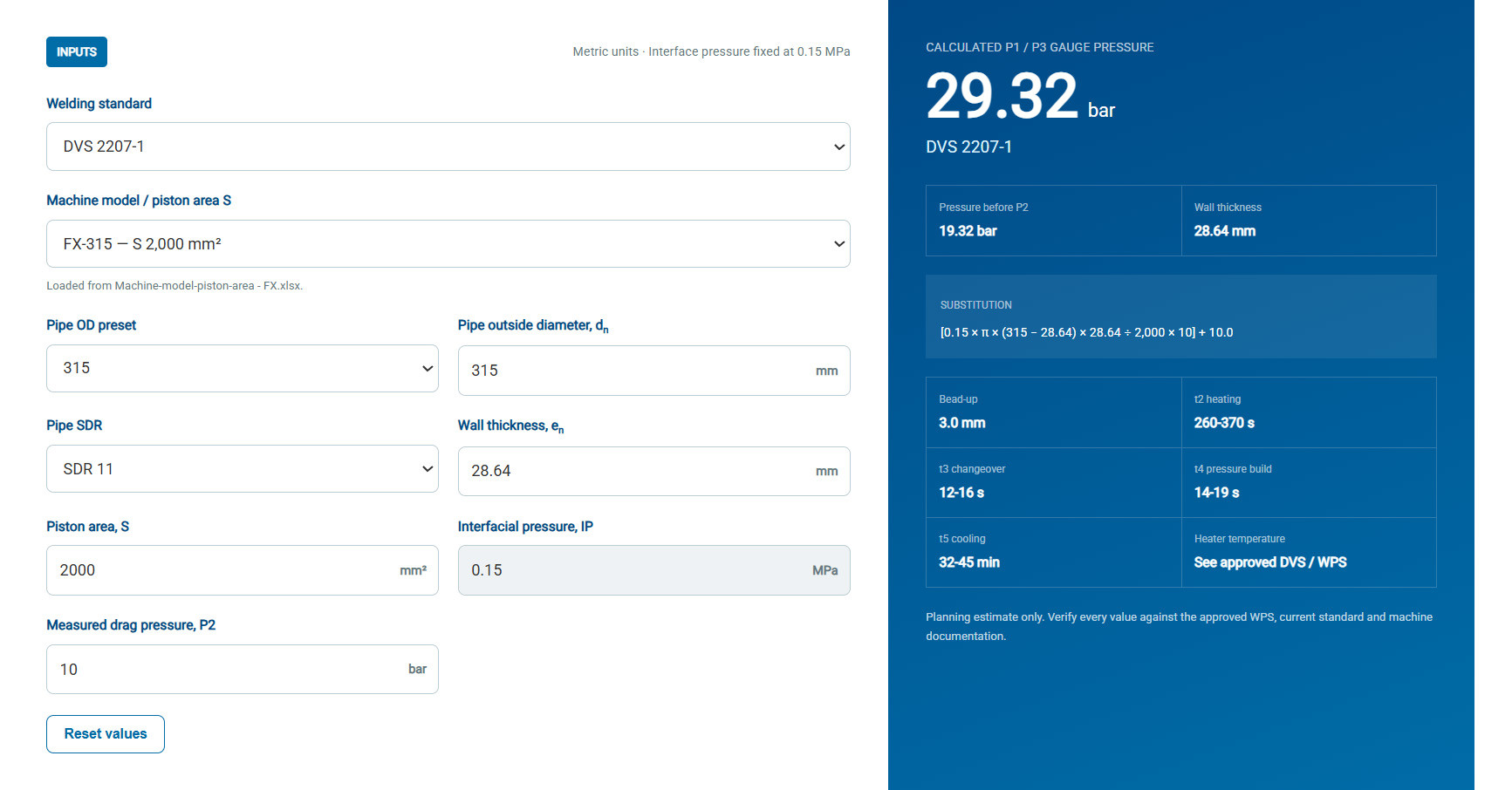
Butt Fusion Gauge Pressure Calculator
Enter or select the required parameters, and the tool will calculate the corresponding hydraulic gauge pressure.
The calculator is located at the bottom of the page.
"Note: The calculator is intended as a practical reference tool. Final welding parameters should always be verified against the applicable welding standard, approved WPS, and machine documentation."